Battery protection IC performance: Latest data & specs
The rise in portable and IoT devices has driven tighter failure budgets for battery systems, making accurate, low-leakage protection essential. Field reports and independent labs show cell-related failures remain a leading cause of returns and field incidents. Designers must prioritize measured battery protection IC performance to limit thermal events, reduce self-discharge, and extend pack life; this guide focuses on repeatable metrics and test methods.
1 — Battery protection IC: role, architecture and core functions (Background)
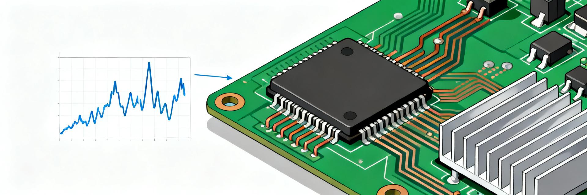
The battery protection IC sits between the cell and external load/charger, monitoring electrical and thermal states. Public datasheets and application notes define the IC as the gatekeeper in the power path. It senses cell voltage and current and actuates series switches or FETs to prevent destructive conditions while providing status signals for system control.
Core protection functions
Overvoltage (OV): Protects cells from excessive charging voltages. OV thresholds and accuracy determine when the IC opens the charge path; precise thresholds avoid overcharging. OV trips a charge MOSFET or open-circuit the pack; threshold error affects state-of-charge management and can accelerate aging.
Undervoltage (UV): Prevents deep discharge. UV thresholds and hysteresis define safe discharge cutoffs. Accurate UV avoids cell reversal and capacity loss; hysteresis ensures stable reconnect behavior after recovery charging.
Overcurrent (OC): Limits sustained excessive currents. OC setpoints and current-limit accuracy determine thermal stress on cells and series FETs. Proper OC control reduces heat buildup and prevents accelerated degradation under heavy loads.
Short-circuit (SC): Fast-trip defense against near-zero impedance faults. Trip-time and energy-to-trip metrics show how quickly the IC and series FET remove fault current. Faster energy-to-trip containment reduces cell venting risk and PCB damage.
Thermal/shutdown: Protects against over-temperature. Thermal thresholds and derating curves dictate safe operating envelopes. Thermal shutdown prevents runaway by disabling paths when internal or ambient temperature exceeds safe limits.
Integration levels and common topologies
Architectures range from passive sensing and discrete FETs to fully integrated protector + MOSFET modules. Trade-offs across datasheets show integrated parts reduce PCB area but can restrict thermal routing. Choose discrete when high continuous current and flexible thermal management are needed; select integrated protectors for compact, low-cost single-cell designs.
2 — Key performance metrics for battery protection ICs (Data analysis)
Electrical metrics form the primary acceptance criteria for specs and performance. Threshold voltages & accuracy, hysteresis, quiescent current, continuous and peak current ratings, short-circuit trip response, current-limit accuracy, and Rds(on) impact thermal loss. Each metric connects to user-visible outcomes: quiescent current drives self-discharge, Rds(on) sets I2R loss, and threshold accuracy affects usable capacity.
Electrical performance metrics
Report threshold accuracy as absolute error over temperature; list hysteresis and repeatability. Small voltage errors (±10–30 mV typical for precision protectors) yield better usable capacity. When specifying, include test temperature points and measurement method to compare parts fairly.
Reliability & environmental specs
Reliability metrics include thermal derating, MTBF indicators, ESD and transient tolerance, and endurance to repeated faults. Datasheet derating curves plus lab fault cycling predict field survivability. Interpret these specs by mapping expected worst-case ambient and fault profiles to the vendor’s derating and endurance numbers.
3 — Benchmarking methodology and representative test data (Data analysis)
Standardized battery protection IC performance tests ensure comparable results. A reproducible matrix includes cell-emulation vs real-cell tests, defined temperature points, steady vs pulse loads, and measurement at sense resistor and IC nodes. Label this as battery protection IC performance tests to produce meaningful comparisons across parts.
| Condition | Metrics |
|---|---|
| 25°C, steady 1C discharge | Quiescent I, continuous I, voltage thresholds |
| -20°C / 60°C, pulse load | Trip time, Rds(on) vs T, current-limit |
| Short-circuit (fault injection) | Trip-time, energy-to-trip, thermal rise |
Key plots and how to present performance data
Use plots that reveal temperature and supply dependence: threshold vs temperature, quiescent current vs supply, trip-time vs fault current, Rds(on) vs temperature, and energy-to-trip. Typical acceptable ranges—quiescent <5–10µA for low-power designs, trip-time <1–10ms for SC depending on FETs. Flag outliers and always annotate test setup and sample lot to ensure reproducibility.
4 — Performance trade-offs by architecture
Single-cell vs multi-cell protection comparisons
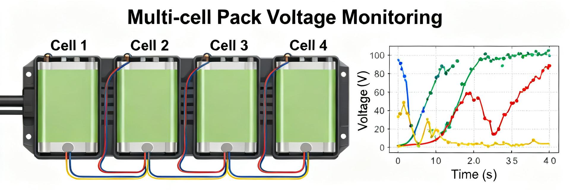
Single-cell protectors emphasize low quiescent current and compactness; multi-cell systems prioritize balancing and cumulative accuracy. Multi-cell stacks amplify threshold error and cumulative power loss. For >3-cell packs, pick ICs with per-cell monitoring or a dedicated BMS to manage balancing and accuracy needs.
Integrated protectors vs modular / external MOSFET approaches
Integrated protectors simplify BOM and layout but can limit thermal routing; external MOSFETs allow optimized heat spreading and lower Rds(on). Typical integrated FET Rds(on) ranges vary—estimate per-architecture values as guidance only. Favor integrated solutions for low-current IoT batteries; choose discrete MOSFETs for high-current tools or EV subsystems.
5 — Design and integration best practices to preserve IC performance (Method/guide)
Hardware-level recommendations
Layout and component choices determine measured performance. Use Kelvin routing to sense resistors, place sense resistor close to the IC, add thermal vias under MOSFETs, and include transient filtering on sense lines. Checklist — (1) Kelvin sense traces; (2) short FET loops; (3) thermal vias and copper pour; (4) RC filtering as needed; these preserve accuracy and limit EMI.
System-level and firmware strategies
Firmware complements hardware for diagnostics and safe recoveries. Implement a watchdog that enforces hardware trip limits, log voltage/current telemetry, and use staggered reconnection algorithms. Coordinate firmware thresholds slightly inside hardware trip points to allow graceful recovery without conflicting with fast hardware trips.
6 — Selection checklist and specs summary for procurement & validation (Actionable)
| Spec | Typical ranges (estimate) |
|---|---|
| OV/UV threshold accuracy | ±10–30 mV |
| Quiescent current | ≤5–20 µA (low-power designs) |
| Continuous current | 1–30 A depending on package |
| Short-circuit trip-time | sub-ms to tens ms |
| Thermal derating | specify curve and max ambient |
Note: Typical ranges are estimates — confirm against current datasheets. Example part codes used in validation: S-8235AAJ-TCT1U (sample reference), S-8235AAJ-TCT1U (repeat reference for traceability).
Pre-production validation steps
Validation must combine bench and environmental screening. Recommended sequence — bench functional tests, thermal cycling, fault injection, production sample lot testing, and short in-field monitoring campaign. Define acceptance criteria (no catastrophic fails, <1% parameter drift) and a short schedule: bench (1–2 weeks), ESS (2–4 weeks), pilot field (4–8 weeks).
Summary
- Measure battery protection IC performance with a standardized matrix; compare threshold accuracy, quiescent current, trip-times, and Rds(on) across temperature to ensure pack safety and usable capacity.
- Balance architecture trade-offs: single-cell integrated ICs favor low-Iq and size; discrete MOSFET approaches favor high continuous current and thermal routing.
- Use the provided procurement checklist and pre-production validation steps to vet specs and catch variability before mass production; always verify against current datasheets and lab runs.
7 — Technical Deep-Dive & FAQ
What is the most important metric when selecting a battery protection IC?
Focus on the metrics that match your failure modes: for portable, low-self-discharge devices quiescent current and OV/UV accuracy dominate; for power tools continuous current and Rds(on) matter most. Combine data from bench tests and thermal profiling to make the final trade-off.
How should I run battery protection IC performance tests?
Follow a reproducible matrix: define cell-emulation vs real-cell, temperature points, steady and pulse loads, and measurement nodes. Record threshold vs temperature, trip-time vs fault current, quiescent current vs supply, and Rds(on) vs T. Keep fixtures and sample IDs consistent for traceability.
How do specs translate to field reliability for a battery protection IC?
Translate datasheet derating curves and endurance numbers into expected behavior under worst-case ambient and fault profiles. Use repeated fault cycling and environmental stress screening to validate MTBF assumptions; simple bench pass/fail is insufficient for production acceptance.
Why are precision overvoltage (OV) and undervoltage (UV) thresholds critical for pack safety?
Precision OV thresholds prevent hazardous overcharging situations, which can accelerate aging or thermal runaway. Reliable UV thresholds prevent deep discharging and cell reversal, ensuring safe recovery and prolonged cycle life.