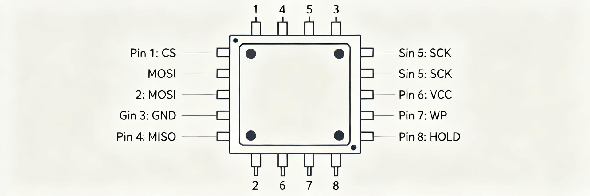
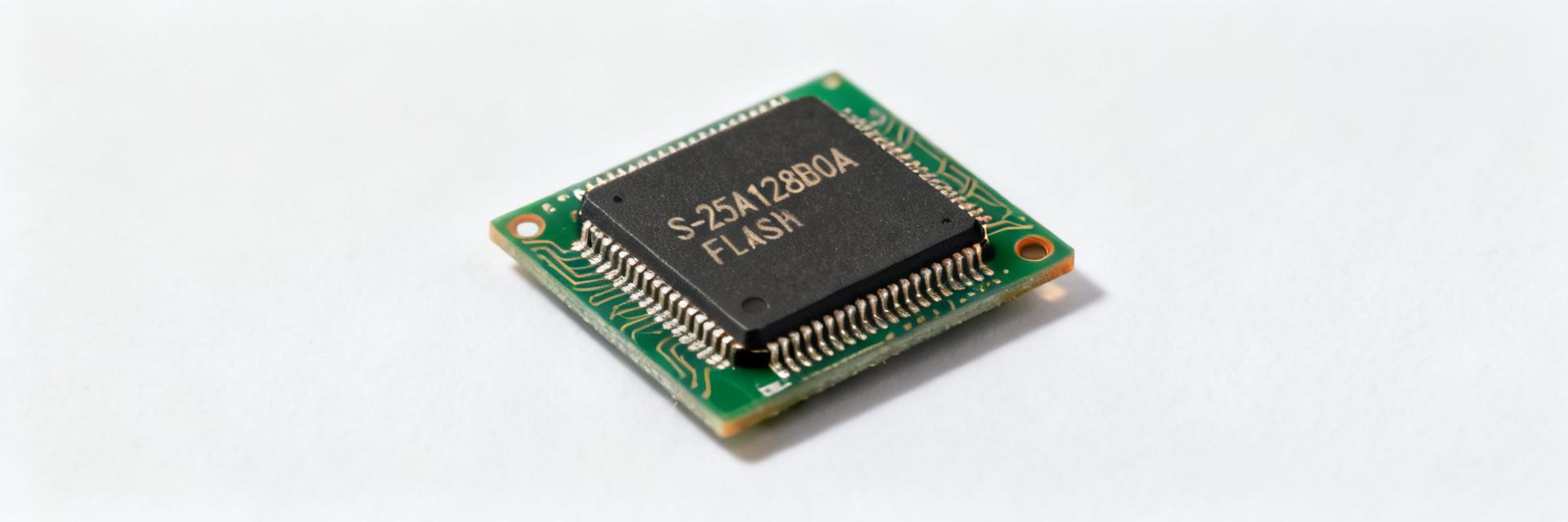
S-25C320A0H-T8T2U3: Характеристики и результаты испытаний на автомобильную надежность
Recent vehicle dependability reporting and in-field telemetry show an increasing share of electronics-related faults, raising scrutiny on serial EEPROM components such as the S-25C320A0H-T8T2U3. Fleet warranty logs and vehicle telematics commonly surface corrupted nonvolatile storage and write-failure traces. Understanding these specs and mapping them to real-world stressors is essential to improving automotive reliability.
1 — Product overview: S-25C320A0H-T8T2U3 key specs
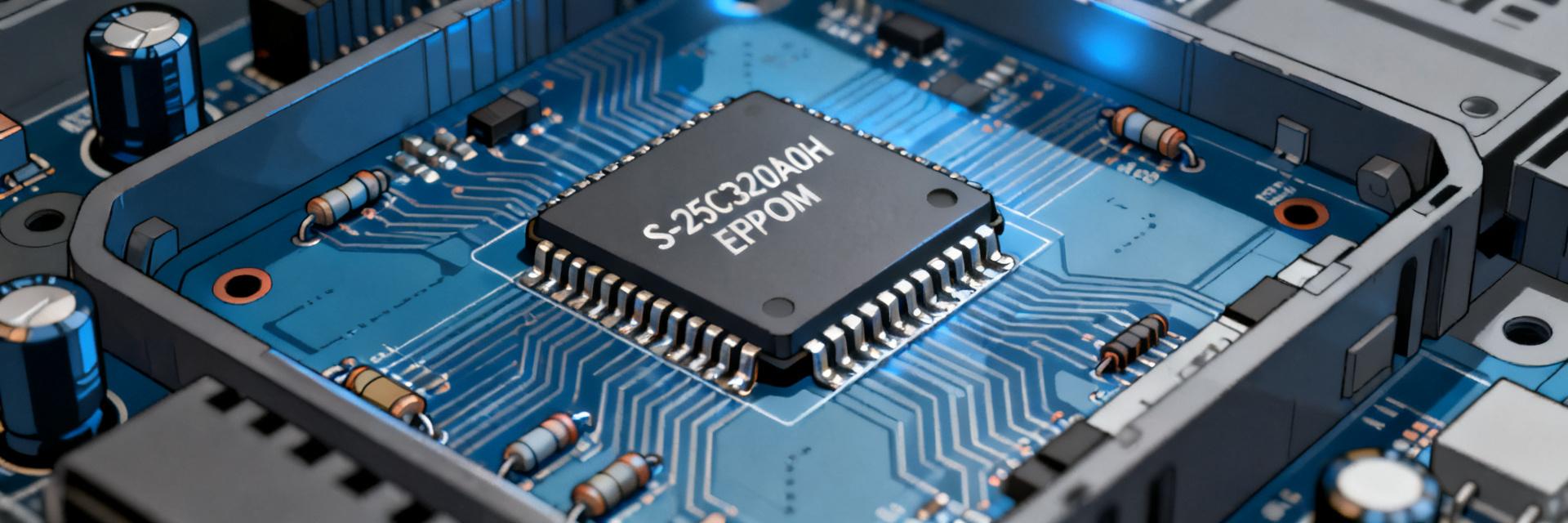
A concise capture of electrical datasheet values enables targeted reliability assessment. These values determine susceptibility to voltage transients, write-window vulnerabilities, and system integration constraints.
Electrical & functional specs
| Spec Parameter | Technical Value |
|---|---|
| Memory Size | 32 Kbit (4096 x 8-bit) |
| Interface Type | SPI (Mode 0, 3) |
| Operating Voltage (Vcc) | 2.7V – 3.6V |
| Maximum Clock Frequency | 5.0 MHz (at 3.3V) |
| Typical Page Write Time | 5.0 ms / page |
| Read Access Time | < 1.0 ms |
2 — How specs translate to in-vehicle reliability
Electrical tolerances and timing specifications have direct system-level reliability implications. Narrow VCC windows or marginal I/O thresholds increase susceptibility to transients during cranking or load dumps. Implement input filtering and local decoupling to harden subsystems when specs approach marginal automotive tolerances.
Voltage tolerance and system-level robustness
When VCC min is near 2.7 V, ECU brownouts during crank can impede safe writes. Recommended mitigations include input LC filtration, TVS clamps on supply and I/O, and 100 nF+10 μF decoupling at device power pins to preserve logic thresholds.
3 — Field reliability findings: S-25C320A0H-T8T2U3
Observed patterns include corrupted data after power loss, stuck bits after thermal excursion, and sporadic read errors correlated with voltage transients. These metrics guide triage—e.g., high incidence of post-crank data corruption indicates inadequate write-atomicity under brownout.
4 — Validation & test methodology
Robust lab validation proves suitability for automotive use. Recommended tests include 1,000 thermal cycles, HAST at specified humidity levels, and write endurance tests to specified cycles with accelerated voltage profiles. Pass/fail criteria include no uncorrectable data errors and no parameter drift beyond spec limits.
5 — Comparative evaluation: S-25C320A0H-T8T2U3 vs. alternatives
Prioritize metrics like endurance and write-time for NV firmware storage, and temp range for safety-critical modules. The S-25C320A0H-T8T2U3 is often selected for its balance of 5.0 MHz clock speeds and standard automotive temperature ratings.
6 — Practical recommendations & checklist
- Design: Use transactional writes with dual-copy commit and validation CRC.
- Hardware: Deploy TVS diodes and 100nF decoupling capacitors near VCC.
- Fleet Policy: Monitor write-error counters and trigger service when thresholds are exceeded.
- Lifecycle: Provision 3–5 spare units per 1k vehicles for field service.
Summary
The S-25C320A0H-T8T2U3 specs set the boundary conditions for in-vehicle performance. Combining targeted lab stress tests with fleet telemetry and adopting practical mitigations materially lowers the incidence of corrupted data and extends the service life of automotive storage solutions.
— FAQ
How does S-25C320A0H-T8T2U3 write endurance affect automotive reliability?
Write endurance limits define how many cycles the device tolerates before increased bit errors; endurance-related failures manifest as stuck bits or CRC failures in the field. Plan for wear-leveling and limit frequent full-page writes in logging-heavy applications to preserve reliability.
What telemetry signals best indicate EEPROM stress in vehicles?
Track error counters (CRC failures), timestamps of failed writes, supply voltage transients, and environmental context such as high-temperature events. Correlating these signals uncovers root causes like brownouts, thermal excursions, or excessive write density.
Which lab tests most reliably predict in-field failures for EEPROMs?
Combined thermal cycling, HAST/humidity, vibration, and power-rail disturbance tests reproduce common in-vehicle stressors; augment with write-endurance bench tests and ESD injection to validate robustness under expected operational profiles.
What are the critical mitigation strategies for SPI EEPROM data corruption?
Implement safe-write firmware patterns including dual-copy commit and validation CRC, delay non-critical writes during transients, and add 100 nF+10 μF decoupling at power pins to preserve logic thresholds under transient events.