
S-93A76BD0A-T8T2U3 EEPROM: Reliability & Specs Report
The S-93A76BD0A-T8T2U3 is examined here to give embedded engineers a focused reliability and specification snapshot for design decisions. Point: designers need compact serial EEPROMs with high write endurance and predictable retention. Evidence: typical 8Kbit Microwire devices claim tens to hundreds of thousands of write cycles depending on grade and test method. Explanation: this report synthesizes datasheet guidance and common test methodologies to produce actionable integration and test recommendations for system-level use.
Point: the goal is a concise, data-driven guide that flags what to confirm in the official datasheet. Evidence: key topics covered include endurance, retention, electrical timing, package constraints, failure modes, and in-field test plans. Explanation: engineers will get a short checklist and test matrix to validate the device against embedded and automotive environmental drivers while minimizing iteration risk.
1 — S-93A76BD0A-T8T2U3 at a glance: key specs & intended applications
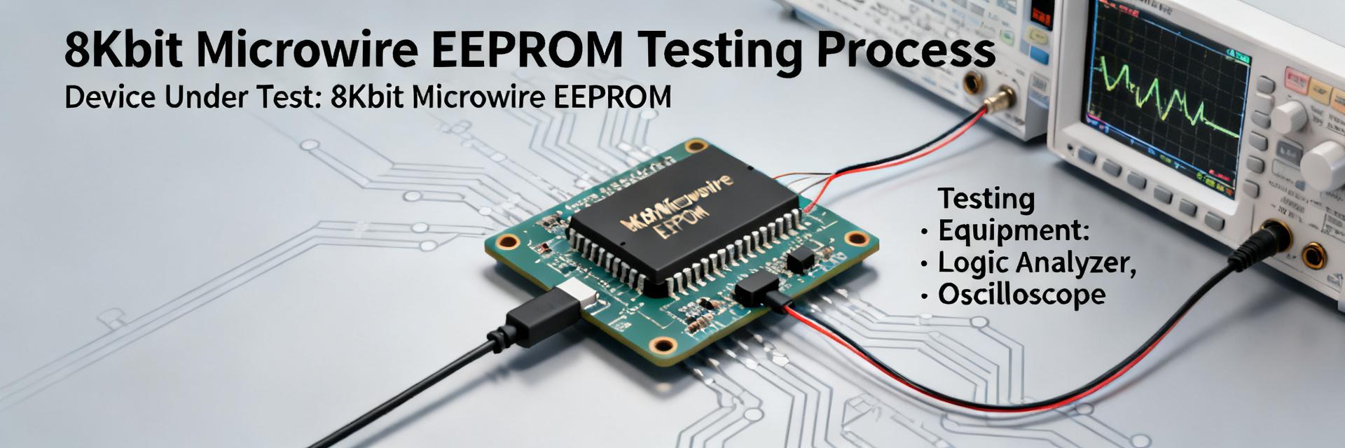
Point: a rapid background helps prioritize verification steps. Evidence: the device is positioned as an 8 Kbit serial EEPROM using a Microwire/3-wire interface in an 8‑TSSOP package with a defined operating temperature window. Explanation: confirm exact values in the official datasheet before procurement (density, interface timing, VCC range, max clock, package outline and temperature grade) because those parameters drive PCB layout and system qualification.
Key specs snapshot
Point: capture a concise spec set for quick validation. Evidence: target entries should list density (8 Kbit), interface (Microwire/3‑wire), maximum clock rate (verify up to ~2 MHz if specified), supply voltage range, typical current consumption, package (8‑TSSOP), and operating/storage temperature ranges. Explanation: these items form the basis of electrical tests, timing validation, thermal derating, and BOM compatibility; always reference the official datasheet for absolute max ratings and test conditions.
- Density: 8 Kbit (byte-addressable map and page write behaviors)
- Interface: Microwire / 3-wire serial protocol
- Clock: verify datasheet for max clock frequency and timing tolerances
- Supply: confirm operating VCC and standby/read/write current
- Package: 8-TSSOP mechanical drawing and PCB footprint guidance
Typical application domains & qualification class
Point: intended uses inform qualification rigor. Evidence: likely domains include embedded control parameter storage, configuration and calibration data, and sensor-module persistent memory, with automotive sensor modules as a potential application if temperature and AEC-like qualification are met. Explanation: environmental drivers—temperature cycles, vibration, and humidity—dictate whether a commercial or higher-grade device is appropriate; for automotive use, verify extended temperature range and any stated automotive qualification.
2 — Reliability metrics: endurance, retention, and stress testing
Point: reliability characterization requires endurance and wear understanding. Evidence: 8K serial EEPROMs commonly specify endurance as program/erase cycles in the tens to hundreds of thousands depending on test pattern and grade. Explanation: endurance testing differs between single-word and multi-byte writes; wear concentrates where writes repeatedly target the same cell, so measurement protocols must include varied patterns and cycle counts tied to application write profiles.
Endurance (program/erase cycles) and write behavior
Point: measure realistic endurance under representative conditions. Evidence: endurance is reported as cycle counts under specific test patterns—random, uniform, or worst-case toggling—with controllers often issuing single‑byte writes for configuration updates. Explanation: track per-address write counts, implement wear mitigation when needed, and validate that test vectors match expected in-field write cadence to avoid over- or under-estimating lifespan.
Data retention, temperature and high-stress performance
Point: retention is temperature-dependent and accelerates under stress. Evidence: datasheets give retention as years at a reference temperature; elevated temperature and biased humidity accelerate charge loss and defect activation. Explanation: perform accelerated retention tests (biased high-temp storage, thermal cycling, and biased humidity) to extrapolate field life, and add retention spot checks to field firmware to detect early drift.
3 — Electrical, timing and mechanical specs deep-dive
Point: electrical and timing details are critical for reliable communication. Evidence: verify supply voltage operating window, input/output thresholds, clock timing (tCH, tCL, setup/hold), and current consumption in standby/read/write modes under stated TA and VCC conditions. Explanation: specify measurement conditions in validation reports, confirm ESD/EMC cautions, and validate the Microwire timing margins with the chosen microcontroller or host interface.
Electrical characteristics & Microwire timing
Point: timing margins reduce bus contention and read/write errors. Evidence: datasheet timing tables define minimum pulse widths and setup/hold times; system noise and supply droop affect threshold crossing and can corrupt serial transfers. Explanation: implement decoupling, controlled rise/fall edges, and, when necessary, add series resistors or shielding to preserve signal integrity and ensure reliable Microwire transfers at target clock rates.
Package, thermal limits and PCB footprint considerations
Point: mechanical constraints change thermal performance. Evidence: 8‑TSSOP outlines include land pattern, pad pitch, and thermal pad guidance; soldering profile and thermal resistance determine maximum junction temperature under power dissipation. Explanation: follow the mechanical datasheet for land pattern, place thermal relief and decoupling capacitors near VCC, and derate performance at elevated ambient temperatures to preserve retention and endurance.
4 — Comparative reliability and common failure modes
Point: neutral benchmarking helps contextualize strengths. Evidence: compare endurance, retention, clock, temp, and write timing against peers using a table of generic devices (Device A/B/C) sourced from datasheets. Explanation: a side-by-side metric comparison clarifies trade-offs—e.g., higher endurance vs. slower write times—and informs component selection when brand or supply constraints exist.
How the device compares to other 8K Microwire EEPROMs
| Parameter / Metric | S-93A76BD0A-T8T2U3 | Generic Device A (93C46) | Generic Device B (93LC86) |
|---|---|---|---|
| Memory Density | 8 Kbit | 1 Kbit | 16 Kbit |
| Interface Protocol | Microwire (3-wire) | Microwire (3-wire) | Microwire (3-wire) |
| Supply Voltage Range | 1.8V to 5.5V | 2.5V to 5.5V | 1.8V to 6.0V |
| Max Clock Rate | 2.0 MHz | 1.0 MHz | 2.0 MHz |
| Target Endurance | 100k to 1M Cycles | 100k Cycles | 200k Cycles |
| Operating Temp Range | -40°C to +125°C | -40°C to +85°C | -40°C to +105°C |
Typical failure modes and mitigation strategies
Point: anticipate wear and environmental failures. Evidence: common failures include wear-out from repeated writes, charge loss under high temperature, single-event upsets in harsh radiation environments, and ESD damage at pins. Explanation: implement wear leveling, CRC or ECC for critical data, brown-out detection and controlled supply sequencing, and system-level redundancy to detect and recover from memory faults.
5 — Integration checklist & in-field testing protocol
Point: provide a hands-on integration checklist. Evidence: essential hardware checks include decoupling near VCC, recommended pull resistor values, trace length and impedance control for Microwire lines, footprint verification against the mechanical drawing, ESD protection placement, and thermal derating notes. Explanation: follow the checklist during PCB review and prototype assembly to avoid common integration pitfalls that cause intermittent failures.
Hardware and PCB integration checklist
- Place a 0.1 µF decoupling capacitor close to VCC pin to stabilize high-frequency spikes.
- Route clock and data lines with short, direct runs and matched trace lengths.
- Include transient/ESD suppression diodes at external programming or connector interfaces.
- Verify layout compatibility against standard 8-TSSOP mechanical land patterns.
- Verify pull-up/down resistors values to guarantee bus stability during host MCU boot states.
Firmware test plan & lifecycle monitoring
Point: implement firmware-level health monitoring. Evidence: recommended tests include burn-in write/read cycles, periodic data retention spot checks, write-count telemetry, CRC checks on critical blocks, firmware fallback images, and persistent failure logging. Explanation: combine these checks with acceptance criteria (e.g., <0.1% uncorrectable errors after X cycles) and use in-field telemetry to schedule preventive maintenance or EEPROM replacement when thresholds are approached.
Summary
Point: conclude with a candid verdict and next step. Evidence: the S-93A76BD0A-T8T2U3 offers a compact 8 Kbit Microwire EEPROM with practical endurance and retention characteristics suitable for many embedded applications; confirm exact specs in the official datasheet. Explanation: engineers should validate electrical timing, thermal limits, and endurance under representative write patterns, then execute the in-field test plan below before production sign-off.
- Confirm datasheet parameters (VCC, max clock, timing) and validate Microwire timing margins in-system to prevent communication errors; include decoupling and ESD protection.
- Run endurance cycles with realistic write patterns and track per-address write counts; implement wear mitigation and CRC checks for critical parameters to extend life.
- Perform accelerated retention and thermal cycling to extrapolate field life; add in-field telemetry for write counts and retention spot checks to detect early degradation.
Frequently Asked Questions
How to validate S-93A76BD0A-T8T2U3 endurance in a lab?
Run controlled write/erase cycle tests that mimic expected in-field write patterns, including single-byte and multi-byte sequences; log error rates and per-address write counts. Use thermal-aided acceleration (elevated temperature) to detect early wear and extrapolate useful life. Acceptance criteria should align to system risk—e.g., zero uncorrectable errors over target cycle count and documentation of test conditions.
What retention tests should be run for long-term EEPROM reliability?
Implement biased high-temperature storage, thermal cycling, and humidity-stress tests that match or exceed field extremes. Periodically read stored vectors and verify checksums or CRCs to detect drift. Use acceleration models to project years of retention at nominal operating temperatures and add in-field periodic verification to catch early degradation.
Which firmware strategies reduce EEPROM failure risk?
Adopt wear-leveling for frequent writes, maintain CRC or checksum protection for critical blocks, record write counts in telemetry, and provide firmware fallbacks and logging on detection of corruption. Combine brown-out detection and controlled write sequencing to avoid partial writes and ensure recoverability after power events.
What are the key interface timing and hardware integration requirements for S-93A76BD0A-T8T2U3?
Key requirements include routing short, matched traces for Microwire signals, placing a 0.1 µF decoupling capacitor close to VCC, using appropriate pull-up/down resistors to stabilize floating bus lines during startup, and implementing transient/ESD suppression to prevent latch-up in noisy industrial or automotive environments.





