
S-19190AGH-M6T1U: Complete Datasheet & Pinout Analysis
In modern battery-backed and supervisory designs, engineers prioritize compact packages, accurate threshold detection, and predictable timing behavior — the datasheet is where those KPIs are validated. This introduction presents a concise entry: S-19190AGH-M6T1U, datasheet, pinout are introduced so a design team can rapidly decide fit, extract key electrical parameters, and plan reference circuits for reliable deployment in embedded power systems.
Point: The article focuses on practical extraction and implementation guidance from manufacturer specifications. Evidence: it synthesizes typical electrical-characteristic interpretation, pin mapping for SOT-23-6, and bench procedures. Explanation: readers will gain actionable checks for thresholds, timing, consumption, layout, and test sequences needed for production-ready battery supervision or reset supervision modules.
1 — Overview: What S-19190AGH-M6T1U Is and Where It Fits (background)
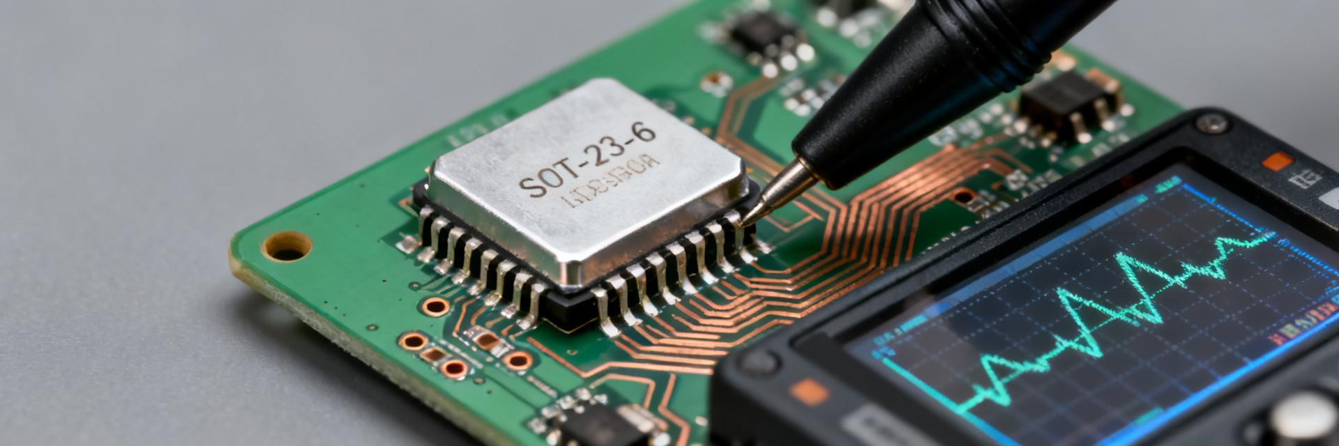
1.1 Primary functions & high-level feature list
Point: The device is a compact voltage monitor and supervisory IC targeted at battery monitoring and reset supervision. Evidence: S-19190AGH-M6T1U datasheet summary highlights low quiescent current, multiple detection thresholds, and SOT-23-6 packaging. Explanation: Typical features include threshold detection, built-in delay circuitry, open-drain reset/flag outputs, and specified temperature behavior that suits backup-battery and power-fail detection classes.
- Voltage monitoring with selectable thresholds and hysteresis
- Low active and standby current for battery-backed systems
- Built-in delay/blanking to avoid false triggers from transients
- SOT-23-6 compact package for space-constrained PCBs
- Target applications: battery monitoring, power-fail detection, reset supervision
1.2 Quick-spec snapshot (how to read the datasheet header quickly)
Point: A rapid-spec lookup helps shortlist the IC. Evidence: At a glance extract supply/operating voltage range, available detection thresholds, package type (SOT-23-6), operating temperature span, and typical accuracy class from the datasheet header and its summary tables. Explanation: Designers should note typ/min/max threshold columns, the test conditions (VIN slope, temperature, load), and the package/marking table to map ordering codes to threshold options.
2 — Datasheet Deep Dive: Electrical Characteristics & Timing (data analysis)
2.1 Voltage thresholds, detection accuracy & hysteresis
Point: Accurate extraction of threshold specs is essential for margin planning. Evidence: Locate threshold voltages as typ/min/max with test conditions (TA, supply tolerance, test current) in the electrical characteristics table. Explanation: Use recommended margining: account for threshold tolerance, temperature drift, and hysteresis by reserving 5–10% headroom in trigger logic or by using staggered thresholds across cascaded monitors to avoid chatter.
| Parameter | Typical | Min | Max | Notes |
|---|---|---|---|---|
| Detection threshold | e.g., 2.8V | 2.7V | 2.9V | Per option; measured at 25°C |
| Hysteresis | ~50mV | — | — | Helps noise immunity |
2.2 Timing, delays, current consumption & thermal limits
Point: Timing specs and current draw define system responsiveness and battery impact. Evidence: Extract delay/response times, active/standby current, and thermal derating notes from timing and power tables. Explanation: Designers should verify delay times under specified input slew rates, measure quiescent at expected battery voltage and temperature, and follow thermal-power derating guidance for SOT-23-6 to prevent overstress in confined assemblies.
| Spec | Typical | Test Condition |
|---|---|---|
| Reset pulse width / delay | 100 ms | Per timing diagram, VIN falling edge |
| Quiescent current (standby) | ~0.5 µA | Specified at nominal VIN, TA=25°C |
3 — Pinout & Functional Pin Description for S-19190AGH-M6T1U (method guide)
3.1 Pin-by-pin table (SOT-23-6) with functional description
Point: Correct pin mapping prevents functional errors. Evidence: Use the package pin map and electrical limits table to list pin number → name → direction/type → short function → voltage constraints; this clarifies the S-19190AGH-M6T1U pinout (SOT-23-6). Explanation: Observe maximum input voltages and output pull-up recommendations; open-drain outputs require an external pull-up sized to the system logic rail and timing requirements.
| Pin | Name | Type | Function | Constraint |
|---|---|---|---|---|
| 1 | VIN | Input | Supply sense input | Max rating per datasheet |
| 2 | GND | Power | Reference ground | Connect to system ground |
| 3 | OUT | Open-drain | Reset/flag output | Require pull-up to logic rail |
| 4 | CNTRL | Input/Config | Threshold select or enable | Observe input clamp |
| 5 | TEST | — | Do not connect/production use | Follow datasheet guidance |
| 6 | VREF | Output | Internal reference (bypass) | Decouple as recommended |
3.2 Typical connection examples and reference circuits
Point: Two reference circuits speed evaluation. Evidence: Minimal hookup: VIN to monitored rail, GND to ground, OUT with 100k pull-up to MCU VCC, decoupling 0.1 µF at VIN. Recommended hookup: add series filter resistor (10 Ω), 10 nF cap at VREF, and a Schottky clamp if rail transients are expected. Explanation: These layouts reduce false triggers, limit inrush, and stabilize reference; place decoupling close to VIN pin and route ground to a single point under the device.
4 — Typical Applications & Design Examples (case study)
4.1 Battery-monitoring and cell supervision example
Point: A worked example demonstrates threshold selection. Evidence: For a single backup cell nominally 3.7 V, choose a reset threshold 5–8% above minimum allowable undervoltage, verify with worst-case component tolerances, and include hysteresis to prevent oscillation. Explanation: BOM includes monitor IC, two resistors for threshold selection if adjustable, decoupling cap, and a pull-up; expected behavior: clean reset asserted when cell < threshold for > delay time.
4.2 System-level use cases: power-fail detection, reset logic, and multi-device coordination
Point: Integration spans simple resets to cascaded supervision. Evidence: Use the open-drain OUT to feed MCU reset and a flag to power-management FSM; coordinate multiple monitors by staggering thresholds or using the CNTRL pin for master/slave enabling. Explanation: For noisy environments add RC filtering, TVS protection, and ensure logic-level compatibility via proper pull-up rail selection.
5 — Integration Checklist, Testing & Troubleshooting (action)
5.1 Pre-layout checklist & PCB placement tips
Point: Layout affects reliability more than many expect. Evidence: Place decoupling caps within 1–2 mm of VIN, keep traces to OUT short, provide thermal relief for SOT-23-6, and add test pads on VIN, GND, and OUT. Explanation: These choices reduce loop inductance, improve transient response, and make in-circuit debug straightforward before fab.
5.2 Lab test procedures, oscilloscope waveforms & common failure modes
Point: A clear bench plan verifies functionality. Evidence: Steps: 1) verify quiescent current, 2) sweep VIN slowly across threshold and record OUT transition, 3) measure delay versus datasheet timing. Typical failures include false triggers from noise (mitigate with C and R), improper pull-up sizing, or thermal drift. Explanation: Record oscilloscope waveforms of VIN and OUT to compare with expected timing diagrams and iterate on filtering or layout accordingly.
Key Summary
- S-19190AGH-M6T1U provides compact, low‑current voltage monitoring suitable for battery monitoring IC and reset supervision; verify thresholds and hysteresis when designing margining into systems.
- Pin mapping for the SOT-23-6 package shows open-drain outputs requiring external pull-ups; follow pinout guidance and decoupling placement for reliable operation.
- Extract timing and current specs from the datasheet tables under specified test conditions; validate with slow VIN sweeps and oscilloscope captures to confirm behavior under temperature and transient stress.
Frequently Asked Questions
What are the absolute maximum ratings for S-19190AGH-M6T1U?
Absolute maximum ratings include maximum VIN and pin clamp voltages, maximum junction temperature, and recommended storage limits; designers must read the datasheet's absolute ratings table and ensure the system never exceeds those limits under worst-case transients to prevent permanent damage.
How to verify threshold accuracy on the bench for S-19190AGH-M6T1U?
Use a precision source to sweep VIN at a controlled rate while logging OUT state and temperature. Compare the transition points to the datasheet typ/min/max, repeat at extremes of temperature and supply, and record hysteresis by measuring rising versus falling thresholds to confirm margins.
What decoupling and PCB placement is recommended for S-19190AGH-M6T1U in noisy environments?
Place a 0.1 µF ceramic decoupling capacitor within 1–2 mm of VIN to GND, add a small series resistor or ferrite if needed, route ground to a single point under the device, and avoid routing noisy power traces beneath sensitive pins to minimize false triggers.
How should the open-drain OUT pin and CNTRL pin be configured for multi-device reset coordination?
The open-drain OUT pin requires an external pull-up resistor to the target logic rail. For multi-device coordination, combine multiple OUT stages in a wired-AND configuration or control downstream steps sequentially using the CNTRL pin as a master/slave enable.
Conclusion
Concise recap: the S-19190AGH-M6T1U is a space-efficient voltage monitor whose datasheet contains the thresholds, timing, and thermal notes designers need; the pinout and functional descriptions guide proper PCB integration, while targeted bench tests and layout checks ensure dependable operation in battery-backed and supervisory designs.





